
Layer geometry
Provide diameter or panel dimensions, layer count, thickness, spacing and the sequence of specified materials.
BOMO METALS · DRAWING-BASED MANUFACTURING
Heat-shield assemblies surround the work zone and form part of the furnace thermal design. BOMO Metals reviews side, end and door-shield geometry, layer arrangement, penetrations and mounting interfaces for custom manufacture or an agreed replacement shield pack. The assembly specification is more than the outline of a single sheet.
Request a custom quotation →Luoyang, China · Project enquiries worldwide
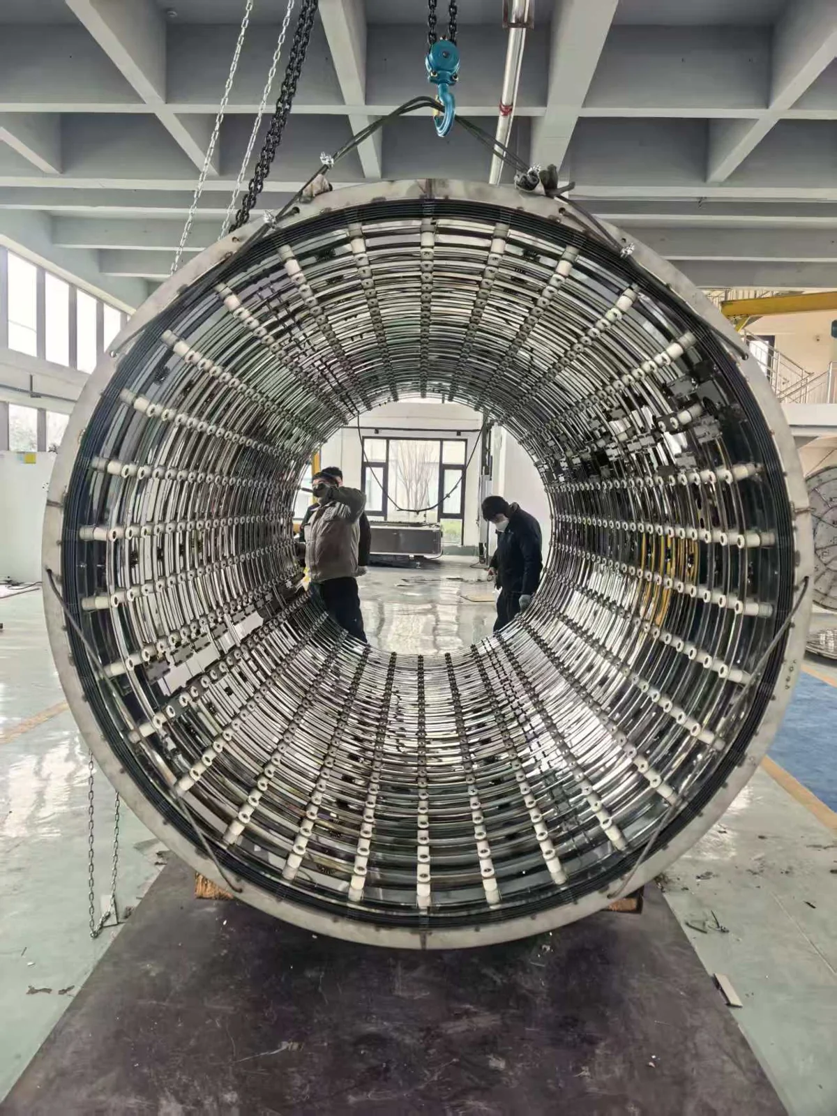
A heat-shield assembly can include side shields, end or door packs, spacers, supports and penetrations. Layer arrangement, spacing and fixing details need to match the furnace design and service conditions.
Provide diameter or panel dimensions, layer count, thickness, spacing and the sequence of specified materials.
Mark sensor, element, support and gas-flow openings. Define seams, overlaps and clearances rather than relying only on an external photograph.
Identify spacers, fixing holes, supports and insertion access. Confirm which items belong to the shield-pack supply.
Send photographs of the hot face, ends, joints and damaged areas, together with dimensions from a stable reference. Identify missing layers or parts, distortion and earlier repairs. Existing condition informs the review but does not by itself identify the cause of heat loss or contamination.
Specify whether the requirement is a replacement to an existing approved layout or a revised design. A change in layer configuration or material needs review against the full thermal and mechanical arrangement.
This page covers the coordinated shield-pack assembly. For individually specified molybdenum sheets, formed shields or replacement metal parts, use the molybdenum heat-shield product page. The two enquiries can share a drawing package while retaining distinct item descriptions.
Include material grade and condition, critical layer dimensions, surface and cleanliness requirements, joint details, tolerances and requested documents. Confirm packaging and handling features that protect thin or formed parts during transport and installation.
There is no universal shield-pack service-temperature or energy-saving promise. Suitability depends on the approved material, design, atmosphere and thermal cycle.
WORKSHOP VIDEO
This workshop close-up shows the internal metallic layers and mounting interfaces of a cylindrical assembly. Use the footage to identify the areas that need separate dimensions, spacing and fixing details in your drawing.
The video is a layout reference; material grade, layer thickness and operating suitability require the approved specification.
Choose material-specific parts when the grade and individual component are already defined. For a coordinated internal assembly or a replacement project, use this hot-zone family and its dedicated pages.
Material grade, condition and compatibility with the furnace duty are confirmed for the approved design. Material melting points are not service-temperature ratings.
A shield pack coordinates multiple layers, spacers, supports, joints and openings. An individual molybdenum shield is a material-specific part; the related product page covers that separate specification.
A photograph helps explain the layout but cannot establish thickness, spacing, grade or hidden layers. These details need a drawing, measurements or an agreed design review.
Record missing or distorted parts, the condition of mounting features and dimensions referenced to stable datums. Describe the process and observed issue so the replacement scope can be reviewed without assuming a failure cause.
Send what is available and mark what still needs review: furnace information, geometry, material, process duty, quantity, destination and the replacement scope.
Discuss your hot-zone requirement →Privacy & drawing information →